![]()
AS-6 AUDIO SEQUENCER
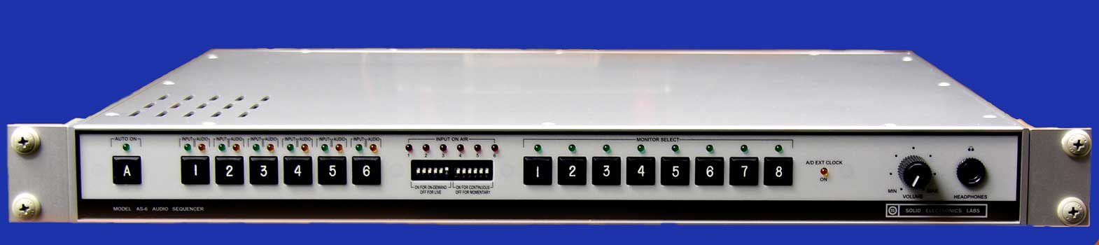
The AS-6 unit will automatically select and route any one of up to six incoming stereo analog or AES digital audio input sources by selected priority and signal validity. The level of the input source priority is determined by which AS-6 unit audio input the associated program audio signal is connected to. Input number one has the highest priority and input number six has the lowest. An audio input signal will not be considered valid unless the signal consists of both a left and a right channel, and has been input to the AS-6 unit for at least (3) seconds. All audio signal input and output selection, routing, and transfer is performed by sealed, plug-in gold-plated reed relays.
Analog or digital input modes are selected by installing the appropriate input module board, allowing the input mode of the unit to be easily changed or rearranged at any time, should needs change. Two input module boards are initially included in the AS-6 base price.
The AS-6 unit will also allow for the automatic starting and stopping of “on-demand” audio sources, such as dial-up remote control units, CD players, or other remote-controlled sources of program audio
The circuits to allow this function are located on plug-in modules, permitting operation on as many of the audio inputs as may be desired. Front panel dip switches program the “on-demand” functions for either “on” or “off” mode, and for either “continuous” or “momentary” control relay contact closures.
The AS-6 unit also provides full time output of the selected right and left channel analog and simultaneous output of the selected AES-3 and AES-3ID digital program feeds, regardless of what type of audio signal is input to the unit. You will always have stereo analog output for analog transmitters and AES digital output for digital transmitters, simultaneously.
A complete audio monitoring system is provided, allowing any one of up to eight incoming stereo analog or up to six incoming AES digital audio program signals to be auditioned with a built in headphone amplifier and a dedicated stereo analog external monitor output port.
Number of audio inputs…………………...up to (6) stereo analog or AES-3 stereo digital
Audio input
impedance……………………Analog inputs – 1 Megohm balanced-bridging
Digital inputs – 10K Ohm
balanced-bridging
The analog inputs are designed to bridge standard 600 Ohm program lines and the digital inputs are designed to bridge standard 110 Ohm AES-3 program lines, both without substantial line loading effect.
Maximum analog audio input level……………………+14 dBm.
Number of audio outputs…
(2) AES-3 110 Ohm balanced main program line outputs
(1) AES-3ID 75 Ohm unbalanced main program line output
(1) 600 Ohm balanced stereo main program line output
(1) 600 Ohm balanced stereo monitor system output
(1) 600 Ohm unbalanced stereo headphone monitor system output
External monitor inputs……..
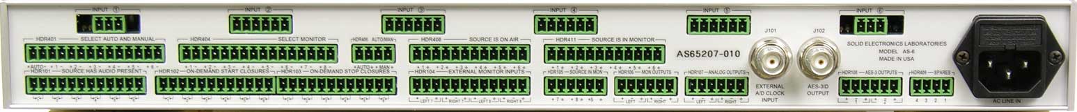
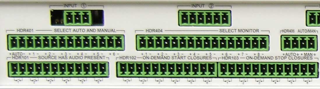
(2) 600 Ohm balanced stereo external audio source inputs All external audio
input and output connections (with the exception of the front panel headphone
jack and the rear panel BNC jacks) are made with Phoenix 3.81 mm (0.15”) plug-in
screw-terminal block connectors on the rear panel.
The AES-3ID 75 Ohm unbalanced main program line output is provided on a BNC connector on the rear panel.
The stereo headphone monitor system output is provided on a ¼” ‘phone jack on the front panel.
Maximum external monitor audio input level……………+14 dBm.
Remote control inputs……….
Optically isolated and designed to be asserted by a momentary pulse or a
continuous application of +5 volts DC to input terminals. (loop current not to
exceed 60 ma.). ( source of +5 volts is provided on AS-6 rear panel).
Tally outputs………………...
Outputs will be “pulled-low” to common ground by internal Darlington
transistor array when appropriate function is asserted. (output loop current
not to exceed 500 ma. and “off-state” voltage not to exceed 50 volts DC
above ground on any tally output terminal). Provision is made for the internal
addition of optional “pull-up” resistor networks to all tally output
terminals." Source has audio present” relay contact closures……………….SPST
normally-open contacts (contact current not to exceed 500 ma.)
On-demand start and stop control relay contact closures……….SPST normally-open contacts (contact current not to exceed 500 ma.)
External A/D clock input……………5 volt peak-to-peak square wave (CMOS logic level) will assert function. Clock frequency input should be 256 times desired A/D sample rate.
Examples:
A/D Sample Rate External Clock Frequency
32 KHz. 8.192 MHz.
44.1 KHz. 11.2896 MHz.
48 KHz. 12.2880 MHz.
Master program D/A and A/D converters………..24 bit, 192 KHz. maximum sample rate 120 dB dynamic range
Monitor system D/A converters………………….24 bit, 96 KHz. maximum sample rate 96 dB dynamic range
Internal A/D master clock frequency…………….11.2896 MHz. for standard 44.1 KHz. sample rate. (other rates optionally available)
Program audio silence threshold sensitivity
(for analog audio
inputs)…………....34 dB below +10 dBm program input level
(for AES digital audio inputs)………40 dB below full scale AES-3 input level
Maximum operating
temperature……………………………………..+45 degrees Celsius
(+113 degrees Fahrenheit)
Call for configuration and pricing